The Garmin G1000 glass cockpit is revolutionizing General Aviation, and now you can see for yourself what all the excitement is about! The Deluxe version of Flight Simulator X includes three aircraft with an optional G1000 glass cockpit variation:
- Cessna Skyhawk SP Model 172
- Mooney M20M "Bravo"
- Beechcraft Baron 58
Pick your plane, step into the cockpit, and prepare to be amazed!
Welcome to the Revolution
The G1000 takes many of the common instruments you're used to seeing on the panel of a small aircraft and displays them on two big computer displays. Everything is displayed in an easy-to-read electronic format, along with some new features too.
More than anything else, the information presented on the G1000's displays—the Primary Flight Display (PFD) and the Multi Function Display (MFD)—will increase your situational awareness. At all times, you'll have a much better picture of the aircraft's attitude, performance, and position.
There's a lot to look at, a lot to play with, and a lot to learn. In fact, the G1000's features rival those found in the cockpits of many airliners! Once you get used to flying with a glass cockpit, it's hard to go back to "steam gauges."
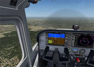
In a simulator, the best way to get up to speed is to dive right in and learn by doing. Luckily, the G1000 is designed to function intuitively. So in this article we'll keep things at a high level. We'll provide an overview of the G1000's major features and how to use them to do most of the basic tasks you're used to doing while flying any airplane under Visual Flight Rules (VFR). While we'll touch on some of the more advanced IFR features, we encourage you to visit www.garmin.com and download the real-world G1000 manuals (free of charge) for a more detailed explanation of the real unit's intricacies.
|
What matters most The G1000 in Flight Simulator doesn't model all of the G1000's features (and new features are being added all the time). It does however model most of what a typical private pilot would use on a typical VFR or IFR flight (using an early model G1000). |
The Big Picture
Ready to learn what all those glowing screens and buttons and knobs do?
Some Flight Simulator pilots prefer the Virtual cockpit for the immersive feeling that it provides. Others prefer the crisp graphics of the 2-D panel. Some use the 2-D cockpit for instrument flying, and the Virtual cockpit for sight seeing. Try using both with the G1000 and see which one you like best.
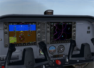
In Virtual cockpit view, you'll be sitting in a 3-D cockpit with the two G1000 displays in front of you. You can zoom in and out by pressing EQUAL SIGN (=) and HYPHEN (-). To look around, use the hat switch on your joystick, press keys on the numeric keypad, or use the thumbstick on an Xbox 360 controller for Windows. One of the best ways to look around the cockpit is the new mouse-look feature. To learn more, see Using the Mouse.
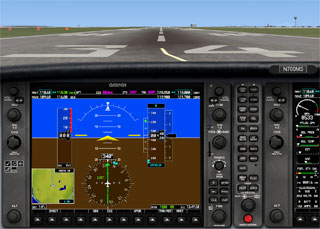
In 2-D Cockpit view (press A to switch cockpit views), you'll be sitting in front of a 2-D G1000 PFD, with just the engine gauges visible on the MFD on the right side of your monitor. You can display additional panels by clicking the control panel icons, or by pressing SHIFT+2 through SHIFT+6. Additional panels include:
|
Don't forget to look outside With two big displays to look at, it's hard to imagine why you'd want to look at anything other than the G1000. But especially under Visual Flight Rules (VFR), you're responsible for keeping yourself separated from other aircraft. Don't fixate on the G1000!For increased visibility in 2-D Cockpit view you can replace the G1000 2-D panel with a mini-panel of traditional instruments (press W), or get rid of the instruments altogether (press W again). You can also make the 2-D panel semi-transparent! To learn more, see Using Views and Windows. |
- Autopilot
- Pop-up Multifunction display (MFD)
- Pop-up Primary Flight Display (PFD)
- Traditional backup gauges
- Engine controls and switches
- Compass
You can drag and resize any of these panels, which is particularly useful if you have multiple monitors. You can, for example, pop-up the MFD, drag it to your second monitor, and resize it so that you can see both the PFD and the MFD at the same time.
Controls and Keys
The PFD and the MFD both feature the same controls and keys, which have been designed to minimize your workload as you access the G1000's sophisticated functionality.
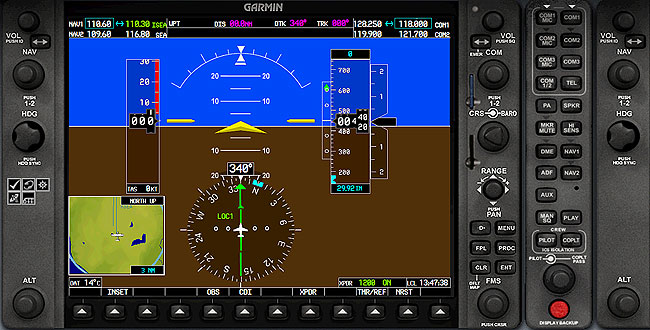
To manipulate the knobs and keys on the G1000, use the mouse just like you'd use your hand in a real cockpit. You can display each control's name by moving the pointer over it.
Knobs
The G1000 includes two types of adjustment knobs: single knobs and dual knobs. Dual knobs have a large knob with a small knob on top of it.


To rotate a knob, move the cursor across the knob. A hand with either a - (minus sign) or a + (plus sign) will appear.
- When the hand with the - appears, click to rotate the knob to the left.
- When the hand with the + appears, click to rotate the knob to the right.
To press a knob, move the cursor over the bottom of the knob until the cursor appears without a plus or minus sign, then click to press the knob.
You can also use the mouse wheel to rotate knobs. Move the cursor over the knob until the cursor changes to a hand, and then roll the mouse wheel to rotate the knob.
Keys
To press a key, place the cursor over the key and click it.

Note: You can also use your computer keyboard to control the knobs and keys on the G1000. There are no keyboard shortcuts assigned by default, but you can map them yourself. To learn more, see Using the Keyboard.
Softkeys
Softkeys are keys that can be reconfigured via software to do different things in different situations. One button can serve multiple purposes. Softkeys along the bottom of both the PFD and MFD provide you with access to numerous functions and pages in the G1000. If there is text above a softkey button, then it is an active softkey, and pressing the button will have an effect.

Note: To return to a previous level of softkeys press the BACK softkey.
The Primary Flight Display
The Primary Flight Display (PFD) provides all the information displayed on a traditional airspeed indicator, attitude indicator, altimeter, vertical speed indicator, horizontal situation indicator, and turn coordinator in a modern, easy-to-scan format featuring a large horizon that's easy to see. The PFD also displays communication and navigational radio information, flight plan data, an inset moving map, outside air temperature, transponder status, and time of day.

Let's explore each of these components.
NAV Frequency Window
The Navigation (NAV) frequency window displays active and standby frequencies for dual VOR/ILS receivers (NAV1 and NAV2), as well as the identifier of a valid, identified navigation aid. The active frequency of each radio is on the right and the standby frequency is on the left. The cyan-colored tuning box indicates which standby frequency will be set using the NAV knob.

|
To swap the standby NAV frequency and the active NAV frequency
|
|
To tune the standby frequencies for the NAV receivers
|
Navigation Status Bar
The Navigation Status Bar displays flight plan information when flying a route created using the Flight Planner or the G1000 Direct-to function:
- Next waypoint
- Distance to the next waypoint (DIS)
- Desired track to the next waypoint (DTK)
- Current track (TRK)
- Navigation annunciations

COM Frequency Window
The Communication (COM) frequency window displays active and standby frequencies for dual VHF transceivers (COM1 and COM2). The active frequency of each radio is on the left and the standby frequency is on the right. The cyan-colored tuning box indicates which standby frequency will be set using the COM knob.

|
To tune the standby frequencies for the COM receivers
|
|
To swap the standby COM frequency and the active COM frequency
|
Airspeed indicator
The Airspeed Indicator displays airspeed on a moving tape. The speed is displayed both numerically and as tick marks on the tape, and speed ranges are shown on a color-coded strip. An airspeed trend vector (magenta line) on the right side of the airspeed tape indicates the approximate airspeed that will be reached in six seconds given any aircraft acceleration.
Vspeed References (set using the TMR/REF softkey) make it easy to fly specific speeds like best glide, best angle-of-climb, and best rate-of-climb. The aircraft's true airspeed (indicated airspeed corrected for non-standard temperature and pressure) is displayed below the airspeed tape.

|
To change Vspeeds and turn the Vspeeds bug on or off
|
Attitude Indicator
The aircraft's attitude relative to the horizon is displayed via the large blue sky, brown ground, and white horizon line that extends the width of the PFD. The Attitude Indicator indicates degrees of pitch and degrees of roll.

Slip/Skid Indicator
The Slip/Skid Indicator is the small bar under the Roll Pointer. It moves away from the Roll Pointer to indicate slip or skid, just like the ball on a traditional Turn Coordinator.

Altimeter
The Altimeter displays barometric altitude in feet on a moving tape. The altitude is displayed both numerically and as tick marks on the tape. An altitude trend vector (magenta line) on the left side of the altitude tape indicates the approximate altitude that will be reached in six seconds given the current vertical speed.
A reference altitude can be set in the box above the altitude tape, and a bug on the altitude tape indicates the reference altitude. The selected barometric pressure is displayed below the altitude tape.

|
To set the Altitude Reference bug
|
|
To set the altimeter barometric pressure
|
When an ILS is tuned in the active NAV radio, a Vertical Deviation/Glideslope Indicator appears on the left side of the altimeter. A green diamond indicates vertical deviation (like a glideslope needle). Marker beacon annunciations are displayed to the left of the altitude reference box.
Vertical Speed Indicator
The Vertical Speed Indicator is to the right of the altitude tape. A pointer indicates the aircraft's vertical speed in hundreds of feet.
Horizontal Situation Indicator
The Horizontal Situation Indicator (HSI) displays a rotating compass card with the aircraft's current heading at the top. A heading bug on the compass rose can be set to a desired heading, and the selected heading appears in a box to the left of the HSI.

|
To set the Heading bug
|
Desired navigational course is indicated by a course pointer arrow just like a traditional HSI, and the selected course appears to the right of the HSI. The Course Deviation Indicator (CDI) moves to the left or right of the course pointer to indicate the aircraft's position relative to the course.

|
To set a course (NAV1 & NAV2 modes only)
|
|
To change navigation sources
|
Turn Rate Indicator
The Turn Rate Indicator is located above the rotating compass card on the HSI. A magenta trend vector indicates the heading predicted in six seconds given the current turn rate. Tick marks indicate standard and half-standard rate turns.

Inset Map
The Inset Map is a smaller version of the Navigation Map on the MFD. Range can be set independently of the MFD Map.

|
To display/hide the Inset Map
|
|
To change the Inset Map scale
|
|
To declutter the Inset Map
|
Outside Air Temperature
The outside air temperature is displayed in degrees Celsius at the bottom left of the PFD.

Transponder Status
The selected transponder code is displayed in a box at the bottom right of the PFD.

|
To select a transponder code


|
Local Time
The local time (LCL) is displayed to the right of the Transponder Status box.

Nearest Airports
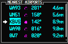
Want to quickly navigate to one of the airports closest to your present position? Just press the NRST softkey, and the Nearest Airports window will display above the Transponder Status and Local Time boxes.

|
To navigate directly to one of the nearest airports
|
The Audio Panel
The Flight Simulator G1000 Audio Panel allows you to toggle your microphone and headset between the COM1 and COM2 radios, and to listen to the audio identifier of navigation aids.
COM MIC/COM keys
To select a communications radio as the active source for audio transmitting or receiving, press the COM1 MIC, COM1, COM2 MIC, or COM2 keys.

MKR/MUTE key
To listen to marker beacon receiver audio, press the MKR/MUTE key. When the key is not illuminated, marker beacon audio is muted.

Aircraft Radio Input keys (NAV1, NAV2)
To listen to navigation radio audio, press the NAV1 or NAV2 keys. When a key is not illuminated, nav radio audio is muted.

The Multi Function Display
The G1000's Multi Function Display (MFD) combines engine information with a full-featured GPS and moving map display. To display the MFD, press SHIFT+3.
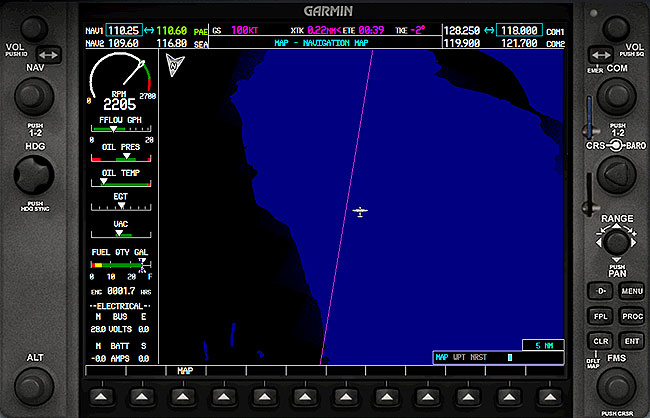
Engine Indication System (EIS)
The G1000 Engine Indication System is displayed on the left side of the MFD and includes gauges, bar graphs, and numeric readouts of engine parameters.

The EIS displays all critical engine, fuel, and electrical indications. The indicators vary by aircraft, but contain all the information found in traditional engine and electrical system gauges including:
- Manifold Pressure gauge
- Tachometer
- Fuel Flow indicator
- Oil Pressure indicator
- Oil Temperature indicator
- Cylinder Head Temperature (CHT) indicator
- Exhaust Gas Temperature (EGT) indicator
- Turbine Inlet Temperature (TIT) indicator
- Fuel Quantity indicator
- Voltmeter
- Ammeter
(The real-world G1000 also includes a System page that displays a numeric readout of critical engine, fuel, and electrical indications.)
What Can I Do with a GPS?
The GPS component of the G1000 MFD can help you to:
- Determine where you are.
- Determine where your destination is.
- Determine how to get from your current location to your destination.
- See a graphic depiction of the terrain.
- Find information about airports, intersections, NDBs, and VORs.
- Locate the nearest airport, intersection, NDB, or VOR.
- Proceed direct to any airport, intersection, NDB, or VOR.
- Follow a VFR or IFR flight plan.
- Fly instrument procedures.
- Be aware of the airspace boundaries in your vicinity.
|
Experience counts If you know how to use the Garmin GPS 500 in Flight Simulator you'll find that you'll have an easy time transitioning to the G1000, as the navigation interface and display of the two units are very similar. If you've never used the GPS 500, we encourage you to give it a try. It's accessible in many Flight Simulator aircraft by pressing SHIFT+3. The GPS 500 is a stand-alone Global Positioning System (GPS) receiver that you can use for navigation and increased situational awareness. To learn more about using the GPS 500, read Using the GPS. |
MFD Page Groups
The GPS/navigation information that appears on the MFD is presented on pages, and you can only view one page at a time. Some pages are organized into groups of related pages, called page groups. Think of page groups as chapters in a book, and pages as the pages within each chapter. There are three page groups modeled in the Flight Simulator G1000. (The real G1000 also includes an Auxiliary (AUX) page group, as well as some additional pages in each page group described below that are not modeled in Flight Simulator.)

The Map (MAP) page group includes:
- Navigation Map page
The Waypoint page group includes:
- Airport Information page
- Intersection Information page
- NDB Information page
- VOR Information page
The Nearest page group includes:
- Nearest Airports page
- Nearest Intersections page
- Nearest NDB page
- Nearest VOR page
Navigating the Pages
To move through the pages of the MFD you'll use the FMS knobs.

|
To select a page group
|
|
To select a page within a page group
|
The bottom right corner of each page provides a graphical indication of which page group and page within that group is selected:

Additionally, the selected page group and page are displayed at the top of the MFD:

You'll also use the following keys as you work with the MFD pages:
| Key | Function |
 |
Clear - Press to erase information or cancel an entry. Press and hold to return to the Navigation Map page at any time. |
 |
Enter - Press to accept a menu selection or data entry. |
 |
Menu - Press to display context-sensitive options. |
 |
Cursor - Press (small FMS knob) to access and enter data. |
Using the Cursor
When the cursor is on, you can access and enter data in different windows using the small and large FMS knobs, and the ENT and CLR keys.
|
To turn on the on-screen cursor

|
|
To scroll down a list of choices or information
|
|
To move the cursor on a page

|
|
To select individual letters and numbers for input at the highlighted cursor location

|
Using the Navigation Map page
The Navigation Map page is the default MFD page and features a large moving map display that shows:
- Airports, airspace, navaids, and land data
- An icon representing the aircraft's present position
- The aircraft's heading
|
To change the Navigation map scale

|
|
To display topographical information on the Navigation Map
 
|
|
To display traffic on the Navigation Map

|
|
To declutter the Navigation Map
|
Direct-to Navigation
The G1000's Direct-to function provides a quick method of setting a course to a destination waypoint (an airport, VOR, NDB, or intersection). Once a Direct-to command is activated, the G1000 will establish a point-to-point (great circle) course line from your current position to the selected destination. The Navigation Status bar at the top of the PFD will provide steering guidance until a new destination is selected, and the CDI will indicate the direct course to the next waypoint (when GPS is selected).
In addition to selecting a destination by identifier, the Direct-to page also allows you to select airports, VORs, and NDBs by facility name. You can also select a Direct-to destination from a list of the nearest airports.
|
To select a Direct-to destination
|
Recentering the CDI needle
If you're navigating to a waypoint using Direct-to and get off course, the Direct-to function may also be used to re-center the CDI needle and proceed to the same waypoint.
|
To recenter the CDI needle to the current waypoint
|
The Select Direct-to waypoint page always displays the nearest airports (to your current position) in the NRST field. Navigating directly to a nearby airport is just a few simple steps away.
Direct-to Shortcuts
Shortcuts are available when using the Direct-to key, allowing you to bypass the use of the FMS knobs to enter the destination waypoint's identifier. You can set a Direct-to course from any page displaying a single waypoint identifier (such as the WPT pages for airports and navigation aids) by simply pressing the Direct-to key and then the ENT key twice. For pages that display a list of waypoints (e.g., the Nearest Airport page), you must highlight the desired waypoint with the cursor before pressing the Direct-to key.
Another tip: once you have one letter or number entered into a datafield, you can type the rest of the word on your keyboard instead of having to rotate the FMS knobs. (This is not a feature of the real G1000, but it saves time when you're "twisting" with a mouse!)
The Active Flight Plan Page
If you create a VFR or IFR flight plan using the Flight Planner, Flight Simulator will automatically load the flight plan into the GPS and activate the plan for use in navigation. (For more information, see Using the Flight Planner.) The Active Flight Plan page provides information for the active flight plan or a Direct-to navigation course.

|
To select the Active Flight Plan page
|
Note: You cannot create flight plans directly in the Flight Simulator G1000. Instead, you must use the Flight Simulator Flight Planner. The flight plan automatically loads into the GPS and is activated for use.
With an activated Direct-to course or flight plan loaded, the Active Flight Plan page displays each waypoint for the flight plan (or a single waypoint for a Direct-to), along with the desired track (DTK) and distance (DIS) for each leg.
On the Active Flight Plan page, you can select any leg as the active leg within the active flight plan (the leg which will currently be used for navigation guidance), using the MENU key.

The OBS key is used to suspend and enable automatic sequencing of waypoints in a flight plan. Pressing the OBS key suspends waypoint sequencing, holds your currently active To waypoint as your navigation reference, and prevents the GPS from sequencing to the next waypoint. A SUSP message displays directly above the OBS key. When you cancel OBS mode, automatic waypoint sequencing resumes, and the GPS automatically selects the next waypoint in the flight plan once the aircraft has crossed the currently active waypoint.
Instrument Flying with the G1000
As you can imagine, the G1000 makes instrument flying a much safer, more enjoyable experience. A thorough discussion of the G1000's IFR capabilities is beyond the scope of this article. If you want to learn more:
- Visit www.garmin.com and download the real-world G1000 manuals (free of charge).
- Visit www.FSInsider.com for articles about all aspects of flight simulation, including instrument procedures and flying with the G1000.
- Read Using the GPS, which explains how to use the G1000's little brother, the GPS 500, for both VFR and IFR flying.
Take it Slowly
If you're a bit intimidated by all there is to learn about the G1000, there's a secret: you don't have to know how to do everything to use it effectively. So pick a G1000-equipped Flight Simulator aircraft of your choice and go flying. Start slowly, and focus on learning to use the Primary Flight Display and Engine Indication System on easy VFR flights. Once you get comfortable flying in a glass cockpit, start playing with the MFD, explore all the page groups and pages, and start using Direct-to navigation.
Then, start planning longer flights with the Flight Simulator flight planner and fly them using the G1000. Do some reading, and when you're ready, dive into the world of glass cockpit instrument flying. That's where you'll see the G1000 really shine.
Most of all, play around, experiment, and have fun!


